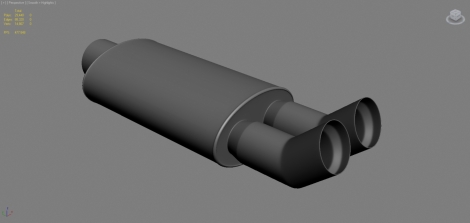
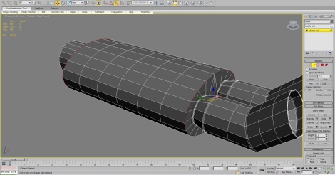
In this tutorial I will show you my work flow on creating a twin tip exhaust pipe like the one below.
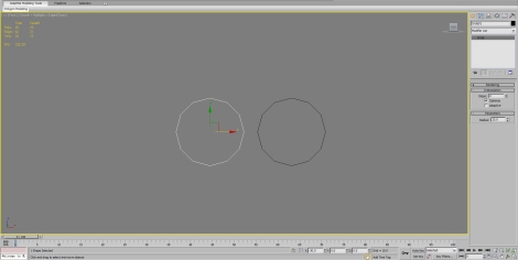
I will be using 3DS Max 2010 but you should be able to follow in pretty much and other 3D software. We are going to start from the tip and work our way across the muffler. First off we will need the front viewport and we want to draw a circle spline and give it a suitable radius and number of sides. I gave mine 12 sides as I am going to use 2 iterations of turbosmooth later and I want it to be smooth. (You can use as many or as little as you want). I moved one circle to the left and cloned it to the right so that I could see how the twin tips would look.
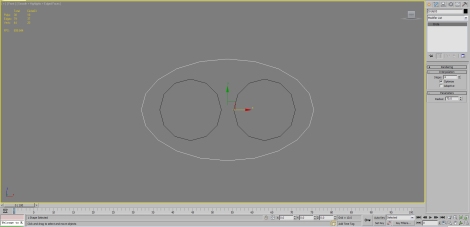
I then created another circle with twice as many sides as the ones before (you will see why in a minute) I then squashed it a bit so it looked like a muffler. These circles are going to be our blueprints for our exhaust.
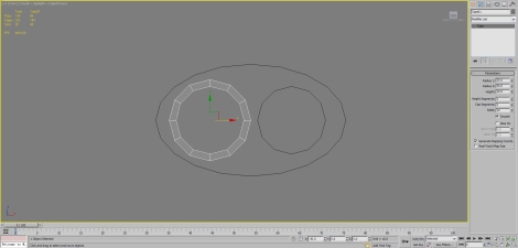
Next we are going to create a tube with the same amount of sides as the smaller circle and locate it in the same place.
Convert it into an editable poly and then delete the back edges so that you are left with a flat circle of polygons and make sure they are in the same place as the circles.
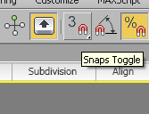
Next we want to set Max up so that it will snap to vertex’s. So across the top of the command panel we want to right click the Snap Toggle button which looks like this:
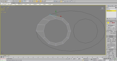
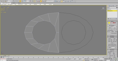
We then want to make sure that only Vertex is selected. Once you have done that make sure that the snaps toggle button is on and we can start some editing. What we want to do is go around moving the outer vertexes towards the larger circle until they snap to the position. Like so:
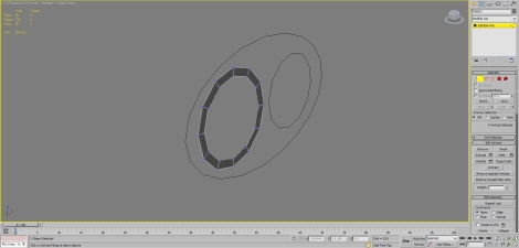
Keep going around until it looks like the image below. Then you can turn the snaps toggle off.
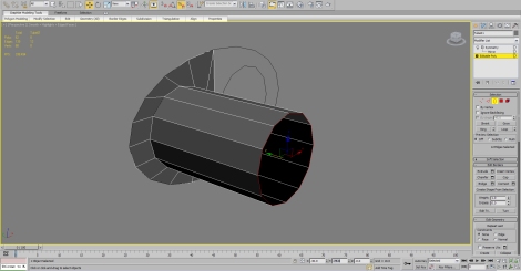
You could now add a symmetry modifier if you wanted. Now it is on to the tips, we are going ring select the inner circle and Shift+Drag it to extrude it. Like so.
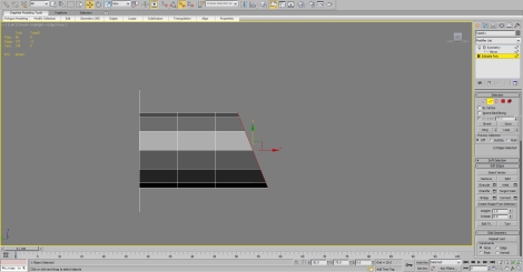
In the left hand viewport give the tip some verticle cuts like and so and the rotate the last loop to your desired angle. You might have to scale it once you have finished to make sure that it stays the same size.
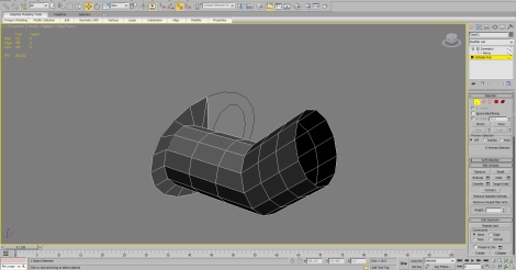
Shift drag your edge loop to any desired height. And give some cuts to keep the meshflow decent.
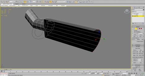
Next we will do a little bit of work using the muffler so select the outer loop of the muffler making sure not to select the middle edges and shift and drag and set it somewhere (note my “Y” position – Your’s does not need to be the same as mine but you will need to know what the coordinates are).
Create another circle using the splines and set it at the location of that last edge loop you created is. In my case it is 225. Make sure it has the same amount of edges as your muffler as we are going to be using the snap function again that we did earlier. Select the muffler edge loop and using the scale function, shift drag to extrude the edge.
Activate the snaps toggle again and snap all the vertexes to the circle spline like so:
Shift drag the new edge loop out as far as you want, we will come back to that part later. Next we are going to define the tips a little more.
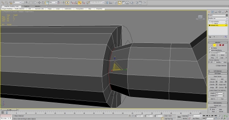
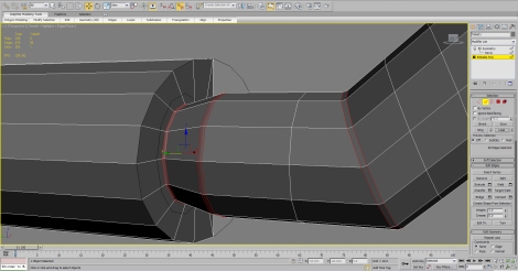
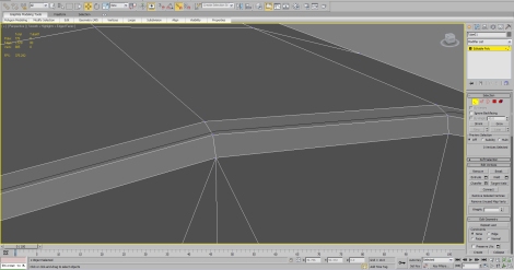
Loop select this edge and scale it so that it give the join a little more definition. Like so:
Then we are going to chamfer these edges as I have here.
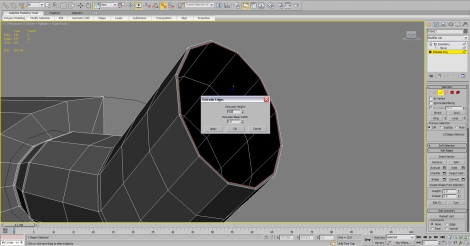
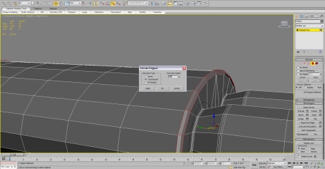
Lets give the inside of the tip a little bit of detail. Select the end edge loop and use the extrude function with something like the following settings:
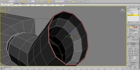
Then go into the left hand viewport again and press F3 to toggle it to wireframe and shift drag that edge to something like this. 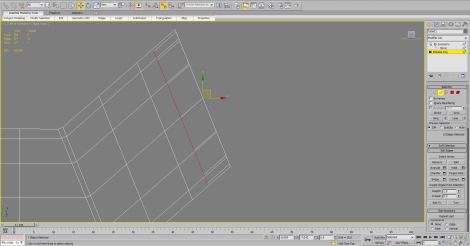
You can make it look however you want, I made mine look like this using a a few shift and drags as well as the scale function. I then chamfered a few edges to add some definition to it.
Now we are going to detail the rest of the muffler. So collapse the symmetry modifier be right clicking and converting to editable poly. First of all we need some more sub-divisions down the length of the muffler so make those cuts.
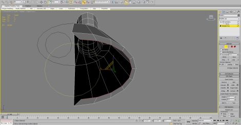
Now we need to select the end loop of the muffler like so:
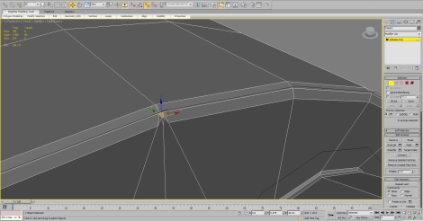
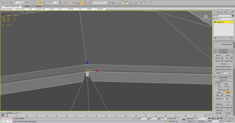
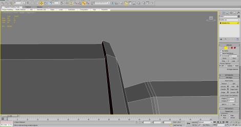
We are now going chamfer these edges with 2 segments. Once you have done that you might have spotted an error like this one shown here but thats not a problem as I will show you how to get rid of that.
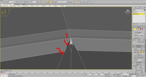
Select the top two vertexes as shown and the click collapse like below:
Then we want to use Target Weld for the other. So right click and the select target weld and then click vertex 1 and then 2 as shown below.
Do this again on the other side then weld them to the middle one remaining. The end result will look like this:
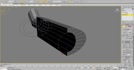
Don’t forget that this would have happened on the under side as well so repeat the steps above to correct that as well. Now to create the seams on the muffler select the newly created polygons like so and extrude them.
Make some new cuts to define the edges, I used ring and the connect to get this edge. Be sure to chamfer the other end of the exhaust as well.
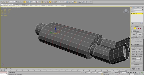
Make any additional cuts if needed. Once done, add a turbosmooth modifier and two iterations and stand back and admire your hard work. Give yourself a pat on the back.
Thanks for watching, I hope you enjoyed.
Thanks for sharing your workflow with us. Awesome!
i like your modeling style clean and smooth but you should do it by using sweep too 🙂 i think it’s easiest way to do
Great work, and as mentioned above, it´s very kind of you to share your methods in such a clean tutorial! I never realy use splines this way, especially with snap, altough it´s very nice way to do it, you can come up with much cleaner and precise results in the end compared to just boxmodeling. I think I should get used to modeling this way more!
Hey, I’ve just seen that your tutorial is up on 3dtotal as well! Great stuff!
Thanks man. Yeah it was nice of them to put it up.
Great Work… Thanks for this
Pingback: Twin exhaust « Dan Rodgers Portfolio·
cheers, max has taken a lot of getting used to from Maya but, for me, seems much better. Got to try and find some more good modelling tutorials now.